| BURNER INFORMATION & TIPS
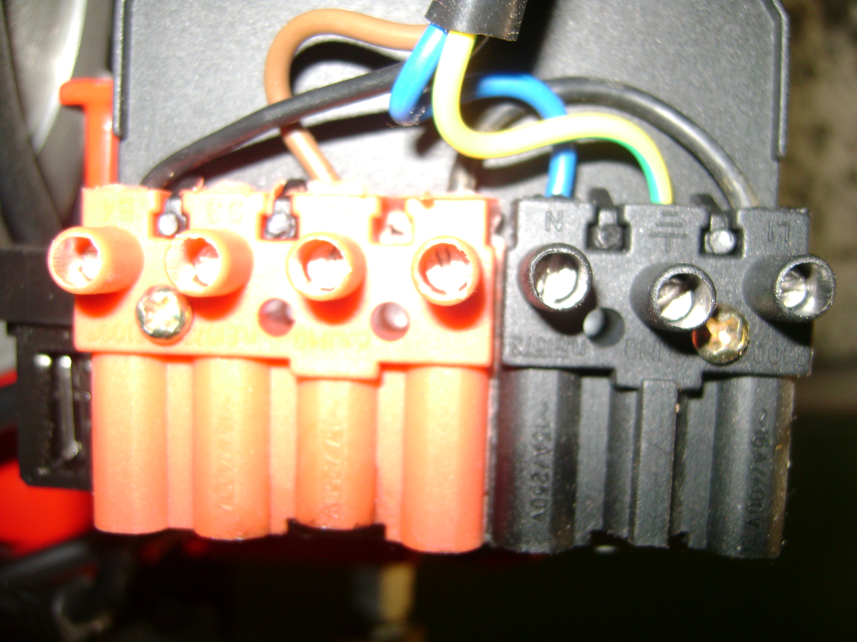
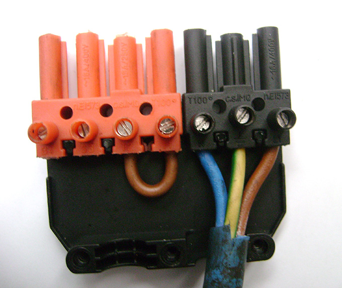
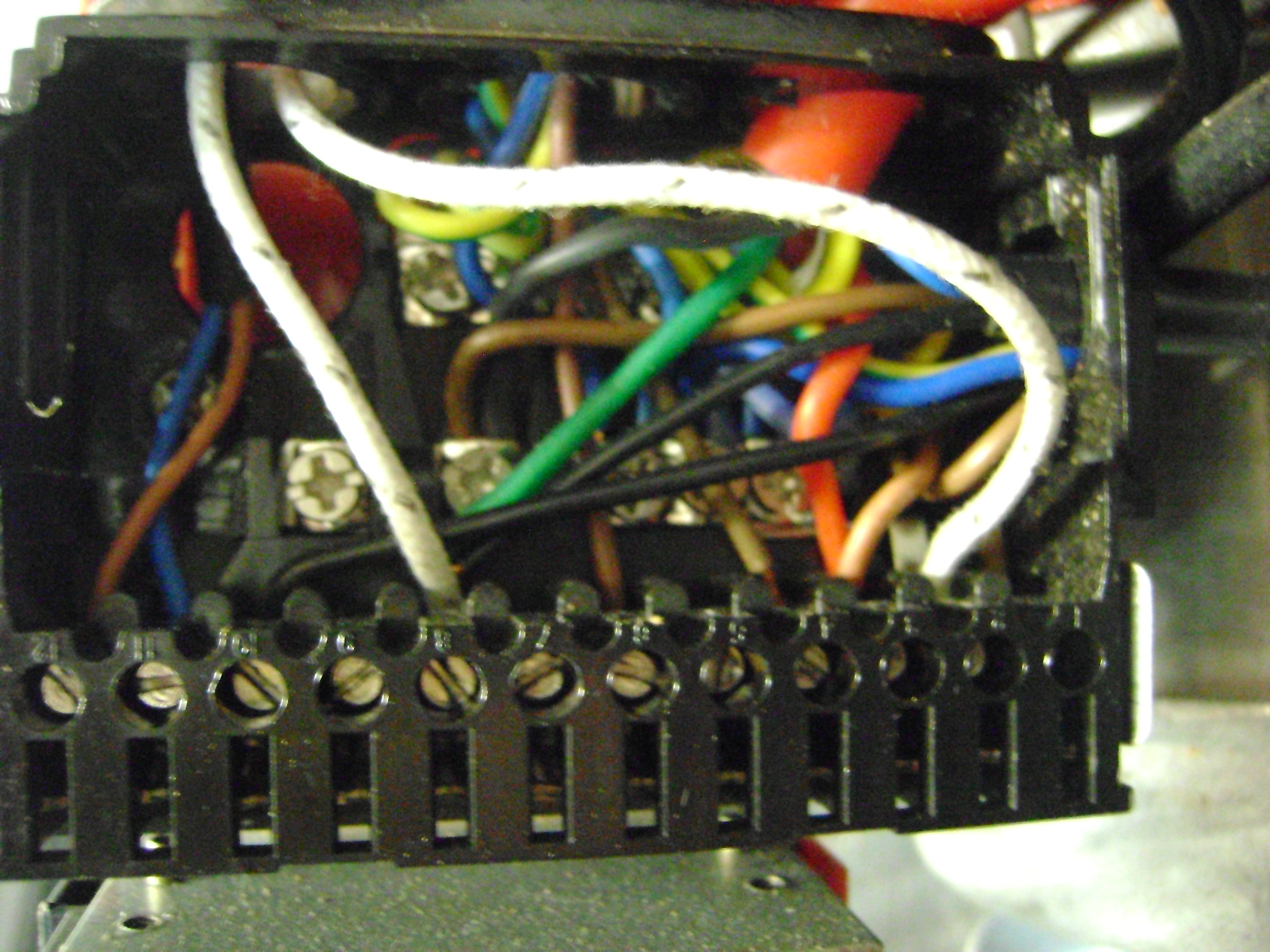
7 Pin Plug Connections as Below The image on the left is the plug attached to the burner and the right image is the mains connection plug.
If you have an external thermostat, e.g. room stat or wireless thermostat, remove the brown link wire. It should be wired in those connectors T1 & T2 where you removed the link.
CONTROL BOX BACK PLATE WIRING Terminal 1...............................................Brown Mains from plug 2..............................................Nozzle Heater 3...............................................Motor and Red to Heater Tank 4...............................................Brown Solenoid 5..............................................vacant 6..............................................Electrodes 7.............................................vacant 8..............................................nozzle heater, green, black oil pump 9..............................................Vacant 10............................................Mains from 7 pin plug 11............................................PE Cell 12............................................PE Cell Join the 2 brown wires ; the pump plug and the wire from the float switch , it may be green on later models. All Blue wires are Neutral , Yellow and green are earth. Before connecting the earth wires just check continuity with earth and the same with the neutral.
For STW120 / STW120P users You must have a minimum of 30cms from the end of the blast tube for the flame length otherwise you will get blow back into the burner which will keep cutting out. If your boiler dose not have the depth to accommodate the flame length a smaller nozzle may be fitted. See Spares. Another solution is to pull the burner out of the firebox by max 10 cms supporting the burner at the rear underneath . This will give more flame depth. However due to the mishandling of the shipment by the carriers , i.e knocks and bumps sometimes problems may occur. The following is the starting sequence:
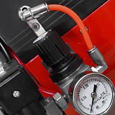
The following may be helpful not only to the newly purchased burner but to Bairan burners already in service : All Bairan burners are fully tested before dispatch. If the Air pressure is showing low on the gauge i.e less than 0.4 kgs /cm sq or 5 psi check that the end cap allen bolts are tight and all air connections are properly connected. and there are no air leaks. Check round the end cap if possible with soapy water which will show up any leaks. If the burner motor runs but makes no attempt to light and goes to reset after about 11 secs make sure the blast tube is in darkness otherwise the Photo Cell / Magic eye will detect that the burner is already lit and pass a message to the control box of a fault. This usually occurs when trying the burner on the bench and not in the boiler or cabinet. Check that you can hear the solenoid open after the 11 secs , if not check the solenoid connections in the plug. The following applies to Bairan burners which have been removed and thoroughly cleaned and then will not light. It is a good practice to run your burner every month on approx 4 litres of Kerosene. This keeps the nozzle holder and nozzle clean. WARNING : Reduce the Temperature to Zero when running on Kerosene Ensure that the Brake plate sits proud of the blast tube by approx 2 mm and the fan air vent is adjusted to the application , usually open 10mm We have been working on these Bairan burners since 2003 so even though you did not buy your burner from us please call 07779017975 if you are having problems. Here are some common Q&As
It is important that the oil level in the oil heater tank is below the level of the nozzle otherwise oil can bleed through the nozzle into the blast tube.
.
How to Get Better Pressure From Your CompressorRemove the end cap, then remove the 6 Allen screws holding the compressor face plate. This will expose the rotor inside the compressor ring. Loosen, do not remove, the 2 Allen screws holding the compressor ring in place, then press the compressor ring tight against the rotor whilst tightening the 2 Allen screws. Ensure that all rotate. Then assemble everything again and you should have a better pressure. If not a new rotor may be required. |
All prices Exclude Duty and VAT
Store Information Main Office: Unit 9, West Float, Dock Road, Birkenhead, Merseyside, CH41 1AE Reg Office: 28 - 30 Grange Road West, Birkenhead, CH41 4DA Company Registration No: 10565693 England VAT No : 290842095 EORI No : 290842095000
Call Us Now: +447779017975 sales@bairan.co.uk © Copyright Bairan Ltd. All rights reserved. Ecommerce Software by Bluepark  |

     |